
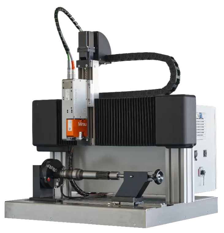
Lead on shaft surfaces is a common cause of leaking radial shaft sealing systems that is barely visible to the naked eye. The Surface/Lead Inspector from TGU Sealing Technology in Stuttgart measures it with the heliInspect H8 in just a few minutes, structure-based and according to FVA Guideline 975 I.
Lead Measurement in Minutes: The Surface/Lead Inspector with heliInspect H8
A radial shaft seal is an inconspicuous component in many technical systems, but its failure is costly: oil leakage, complaints, and downtime. One of the most common causes is not the seal itself, but the surface of the shaft it runs on—the so-called sealing counterface. Fine, oriented structures created during the shaft grinding process act like a pumping thread during operation, pumping fluid past the sealing lip. In sealing technology, this phenomenon is known as lead.
TGU Sealing Technology from Stuttgart is a specialist in sealing technology, originating from the research activities of the Institute of Machine Elements (IMA) at the University of Stuttgart. The Surface/Lead Inspector is a measurement system developed there that quantitatively, guideline-compliant, and above all, quickly detects lead. The core is our 3D sensor heliInspect H8. In this article, we show what lead is, how it is measured, and why fast 3D topography measurement makes the difference.
What is lead, and why is it so insidious?
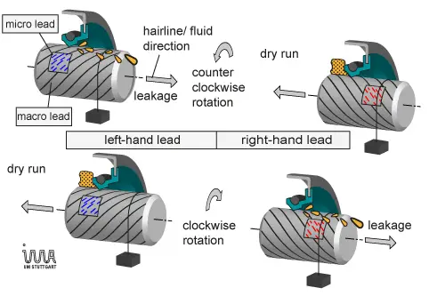
Lead refers to pumping-active surface structures of the sealing counterface that redirect the flow in the sealing gap axially during dynamic operation. The orientation is crucial: if grinding marks or other structures deviate from the circumferential direction of the shaft, a right-hand or left-hand lead is created depending on the orientation.
The pumping direction depends on the shaft’s direction of rotation and the lead orientation. If the structure pumps outwards, leakage occurs. If it pumps inwards, the sealing contact dries out, resulting in insufficient lubrication, increased friction, and thermal damage to the sealing ring and shaft. Both cases lead to the failure of a sealing system, and both are not visible to the naked eye. Lead can only be reliably assessed by measurement.
The FVA Guideline 975 I: A Common Language for Lead
How lead is measured and evaluated is regulated by FVA Guideline 975 I “Surfaces/Lead – Shaft Seals” from the Research Association for Drive Technology. It was developed and written by the Sealing Technology research area of the Institute of Machine Elements (IMA) at the University of Stuttgart. It summarizes the current state of technology and research, defines a uniform terminology, and describes a continuous workflow from drawing specification to measurement and measurement report. This makes it a reliable basis for consistent quality assurance of shaft lead and for systematic damage analysis on sealing counterfaces.
The guideline knows two ways:
- The thread test is the traditional, primarily qualitative quick test. A weighted thread is placed around the shaft to indicate any pumping effect and allow for the estimation of a theoretical lead angle. However, it is not possible to differentiate between individual lead categories.
- The structure-based lead analysis quantitatively evaluates micro and macro lead from optically acquired 3D topography data. Individual grinding marks and structures are segmented and measured in terms of angle, depth, and volume. The result is reproducible characteristic values such as lead angle, lead depth, and theoretical pumping cross-section. The roughness of the visible surface is additionally characterized according to DIN EN ISO 25178.
The second method requires one thing: a sensor that delivers 3D topographies with micrometer resolution fast enough to capture an entire shaft in a reasonable amount of time.
The Surface/Lead Inspector: all guideline methods in minutes
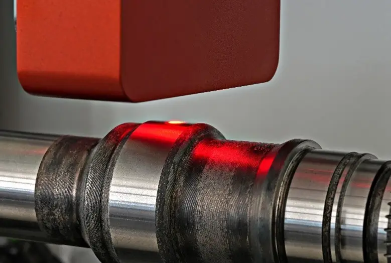
This is where the Surface/Lead Inspector comes in. The shaft is mounted in the device and non-contact scanned under the sensor. The heliInspect H8 sensor is used, a white light interferometer that provides a complete 3D topography with micrometer resolution per scan.
The system covers all methods of the FVA Guideline 975 I. Because the heliInspect H8 captures height information across an area and in a single pass, the device can scan a dense measurement grid in axial and circumferential directions around the entire shaft, instead of scanning profile by profile. For manufacturing, this means: lead measurement no longer just as a random sample in the lab, but cycle-time-relevant in quality assurance.
The device accommodates shafts up to 200 mm in diameter, 380 mm in length, and 20 kg in weight, and at 600 × 700 × 900 mm and 70 kg, it is compact enough for use close to production. Easy-to-use measurement software guides through the measurement and creates the measurement report with the lead characteristics and a 3D visualization of the surface.
More than Lead: Roughness from the Same Measurement
Since the sensor provides complete 3D topographies, further analyses are possible without re-clamping. The Surface/Lead Inspector determines 2D roughness parameters such as Ra, Rz, and Rmax according to ISO 4287, as well as 3D parameters according to DIN EN ISO 25178. Wear on run-in shafts can also be quantified: the depth and width of a seal’s wear track are determined directly from the topography, an important tool for damage analysis.
Conclusion: The Sensor Technology Makes the Guideline Practical
The FVA Guideline 975 I describes how lead should be fully and reproducibly evaluated. The Surface/Lead Inspector shows that this requirement can also be implemented in industrial practice with a fast 3D sensor: all lead categories, all guideline methods, in minutes instead of hours. For us, the device is a good example of how a fast topography measurement with the heliInspect H8 becomes a complete inspection system.
Further Information
- Surface/Lead Inspector, lead measurement as a service, and brochure:
TTI GmbH – Lead Measurement and Surface/Lead Inspector (device) - Live Demonstration at the Heliotis Booth at Vision Stuttgart
- Our 3D sensor: heliInspect H8
 Heliotis AG